Sunday, August 12, 2018

Some AREDN progress

We have been working on bringing up an AREDN mesh network at ARRL HQ and here at AA6E.  AREDN, the Amateur Radio Emergency Data Network, has developed from the HSMM project (High Speed Multimedia, see web sites here and here.)  AREDN supports a "mesh network" running under FCC Part 97 (Amateur Radio) rules on allocated frequencies some of which are close to standard "WiFi" (2.4 and 5 GHz).

Ubiquity Nanostation Loco M5 AREDN node
What is mesh networking?  Simplified, it is a way to interconnect more or less randomly located network nodes that may come and go, such as in response to emergency requirements.  Each node may originate data or may relay data to adjacent nodes. Networking software automatically routes packets by the best paths through the mesh, from source to destination.  Certain mesh nodes may have gateways to other networks, such as the commercial Internet.  Certain nodes may have special servers (web, email, file, etc.) that are made available to the network.  In general, AREDN mesh networks are set up to be independent of commercial communications services as much as practical.

At AA6E and ARRL, we have implemented a test network to learn about AREDN technology and to try out configurations that might support a variety of routine and emergency communications needs.  The first setup uses up to 4 Ubiquiti NanoStation Loco M5 devices with custom AREDN software.  These form a small-scale mesh, currently all within the ARRL Laboratory.

A test bed setup at AA6E uses two of these nodes to demonstrate network capabilities.  Below is a block diagram of the tested network.
The AREDN network is at the right.  One Loco M5 device supports a laptop computer (where I am writing this article).  Through the radio link at 5.9 GHz, the two Locos support a bit stream of up to about 30 Mb/s using a 10 MHz RF channel.  As seen by the laptop, the Loco provides an IP address through its own DHCP server.  Traffic is routed to the second Loco, which in turn supports two VLANs (partitions of a single Ethernet connection).  One is a generic "LAN" connection that will support Ethernet devices like the Raspberry Pi which is acting as a small webserver for our test.  The Pi will also support SSH, VNC, and many other services as needed.

The second switch port supports another VLAN for "WAN" connections, e.g., to the Internet.  Through the Internet router it obtains an address on the household LAN.


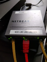
L to R: Raspberry Pi 3; Netgear GS105E VLAN-aware switch; Toshiba Laptop

This setup demonstrates many of the functions we would need in an operational network.  We still need to set up facilities for node to node bridging that we would need to build up a larger network, supporting multiple operating bands, etc.

There is nothing "new" here.  It's all been done elsewhere, but we are climbing our learning curve.

Saturday, April 28, 2018

Gone Streaming. Sorry, Comcast.

So sorry to hear that the cable TV industry is suffering because of the growing defection to streaming media services.  See this recent Fierce Cable article. We seem to be entering a meltdown, where increasing cable prices encourage more of us to "cut the cable" and go to streaming solutions.  That means that cable companies have to increase their rates, which leads to more defections.

You don't want to be the last one to switch over in a game like this.

We aren't the first by any means, but our sky-high bill finally got to be too much when the last of our introductory discounts disappeared.

Technically, the Comcast service in our area is very good.  Internet performance has inched up over 250 Mb/s.  Unfortunately, the monthly charge is running around $1 per Mb/s.

So we had an abundance of bandwidth and a similar abundance of channels -- most of which we never used.  The Internet bandwidth is sweet when I want to download a new Linux DVD every 6 months, but how much is that really worth?

TL;DR. We have just dropped cable video and phone service and cut back our Internet speed to 60 Mb/s -- quite enough for our small household.  These changes cut our Comcast payment by 70%!

The new system is built on a Netgear CM600 modem, an Asus RT-N66U WiFi router, an Ooma Telo VOIP box, and a Roku streaming device. (Our nice Sony HDTV predates "smart TV".*) In addition, we're watching more over-the-air TV, mainly to get the PBS Newshour live.  (PBS hasn't figured out how to live stream, it appears.) In this location, we need an amplified antenna that mostly works for us indoors, but it will need to be installed outdoors for solid performance.

The thorny issue now is how to make sense of the many streaming services.  People worry about what will be happening without "net neutrality".  The Internet is likely to fragment into walled gardens.  As others have pointed out, this already is happening in the streaming market.  Do I want Amazon Prime, Netflix, Hulu, CBS Now, etc.?  There are several providers for live streaming TV channels, too. Each of these has some interesting content.  Even if I didn't mind paying for all of them, the data management gets to be overwhelming.  There is no simple navigation or program guide I know of that crosses those boundaries.

Brave new world?  Chaos?  All of that. Glad to help the cable industry find its destiny.

* Smart TV: I worry that the "smarts" get obsolete well before the "TV" does.  Integrating them should help simplify the user experience, but the quick obsolescence is a worry.

Monday, April 09, 2018

Frequency Measurement Test

The old way: BC-221 meter
April 6, 2018 was my second attempt at the ARRL Frequency Measurement Test in which amateurs are invited to measure the exact frequency of a test signal transmitted from a central site. The first time, years ago, I came out OK with a manual procedure using my old TenTec Orion radio, carefully calibrated against the US NIST Time and Frequency Station WWV. Measurement accuracy depended on an imprecise estimate of the WWV calibration compounded by an imprecise measurement of the W1AW test signal.

This time, we've upped the ante, using the FlexRadio Systems 6500 transceiver (an SDR radio) with its GPS Disciplined Oscillator as a master frequency reference.  The reference is said to be accurate to some parts in 1012, though we have no way to verify that number at this time.  If the receiver is tuned to a known frequency just below the test signal in upper sideband mode, so that the received signal shows up as an "audio" tone.  (In this SDR receiver, there is no "audio", since everything is digital.  That bypasses various audio measurement problems that might otherwise have cropped up.)  The fldigi software package is used in its "spectral analysis" mode to accurately measure the offset, combined with the known local oscillator tuning, to yield a good measurement of the unknown RF frequency.  The software outputs an Excel CSV file that records time and best-fit frequency each second.

Here in Branford, CT the antenna for 20 M is a 3-element SteppIR at 40 ft pointed west. For 40 M and 80 M the antennas were dipoles oriented NW-SE, more or less.

This exercise involved transmissions on the 20, 40, and 80 Meter amateur bands from K5CM in eastern Oklahoma.

RESULTS

The actual numbers as transmitted are reported on the FMT results page for 2018.

Band  F Measured (Hz)  F Actual (Hz)   Error (Hz)
20M  14,121,963.42 +/- .08*  14,121,963.34   +0.08
40M   7,064,257.09 +/- .20*   7,064,257.06   +0.03
80M   3,598,169.5**   3,598,169.73   -0.23

* Error bar quoted is 1/2 the total peak-to-peak frequency excursion in the 2 minute test transmission.
** 80M results were compromised by a data handling problem.  Precision is reduced, and an error bar could not be estimated.

WWV reported geomagnetic conditions Kp=2 and Ap=9 during the test.

The graphs at the right show the (almost) raw data measured on the 20 and 40 M bands.  The 20 M signal strength was quite good, touching S9+10 dB, and the measurements appear largely free of statistical noise. The major feature is an sine-like variation that presumably reflects true changes in the signal data path.  I believe that the "glitch" at the left is an artifact of an initial mis-adjustment of the radio.  It was left out of the average calculation. (Ignore the "even samples" tag.)

The 40 M signal was about S8, i.e. up to 16 dB weaker than on 20 M.  This probably produced much of the short-period noise on the graph. However, we might also expect the ionosphere to produce more variability on the lower frequency.

For 20 and 40, we calculate a simple average frequency, after eliminating the initial points on 20 M.  Note that we might have done better of we could weight the samples according to instantaneous signal strength.  There are two sharp dips in the 40 M data that may well have arisen from deep signal fades.  If they were eliminated, we would have a slightly higher frequency estimate, which would have increased our final error value.

Because of the problems with the 80 M data, there is no meaningful graph to plot for that band.

DISCUSSION

The final error (Measured - Actual) is under 0.1 Hz for the two fully analyzed bands, while the 80 M error is -0.23 Hz based on fewer data points.  These are surprisingly good, leaving relatively little room for improvement given the "noisiness" of ionospheric propagation conditions.  Presumably, we might get a somewhat better measurement if we had a longer test run, perhaps 5 or 10 minutes or more, or if we got lucky and had a period of super-stability in the ionosphere.

Sunday, March 04, 2018

Annals of Provisional Engineering (GPS)

The GPS antenna provided by Flex Radio Systems for their GPSDO add-on module is an indoor-style "biscuit" measuring about 1 x 2 inches.  It comes with an adhesive patch that is meant to secure it to an indoor window.

My available window had a rather marginal sky view, and the GPS was not locking up very well.  So before going out for a "professional" outdoor antenna, it seemed a good idea to try the one on hand.

Having achieved a certain age, I have a lot of containers for medical prescriptions that I've been saving for some reason.  One of the larger ones nicely fits the biscuit, along with some bubble wrap as a filler.  The cap used to seal the contents quite well, and it does so even after being sliced to allow the RG-174/U style coax to pass through.  (The coax is permanently attached to the antenna.)

Long story short -- the antenna and "radome" attaches to a convenient metal mast about 5 feet off the ground, facing upward.  The duct tape system won't last forever, but it's fine for a temporary setup.  GPS reception is now quite solid.

It has survived a recent "bomb cyclone" wind and rain event that downed a fair number of trees in our area.

Friday, February 23, 2018

GPS is Looking Up

GPSDO unit in Flex 6500, cover removed

Flex 6500 GPSDO attachment area
This is a bad news, good news story.  Last year, I purchased the GPS Disciplined Oscillator (GPSDO) option for my Flex 6500 transceiver. This is meant to be a user-installable device that receives the GPS signal (1.2 - 1.5 GHz), derives very accurate time (UTC) and frequency (10 MHz) for use by the transceiver.  And, of course, it reports your geographical position (latitude, longitude, and height above sea level) and speed.

As you can see from the photo, the GPSDO appears to be based on custom version of a Jackson Labs GPSOCXO (Oven Stabilized Crystal Oscillator) module.  It's the green board that attaches to a blue Flex-produced interface board. The GPSOCXO specifications are available as a PDF, while general information is here.

I am now on my third GPS unit.  The first was a "reconditioned" unit, because new units were then in short supply.  It never worked for me -- it would not detect satellites.  Flex then supplied another unit, which worked well.  It detected satellites, locked up, and appeared to deliver good frequency stability. But, over time, it grew hard of hearing.  It dropped out of lock more and more and finally would not lock at all, though it continued to supply 10 MHz in "holdover" mode.

GPS Status, SSDR software
Fortunately, my unit failed just before the warranty period expired, so I was able to get a replacement without (financial) trouble.  Now my third (and hopefully last) unit is perking along. The good news!

Currently, I use the Flex-supplied simple "patch" active antenna attached to a nearby west-facing window.  Typically, I track 7-8 satellites out of 10-11 "visible".  We might be able to squeeze out more performance by installing a larger outdoor antenna.


Why use GPS?

The standard Flex TCXO is fine for nearly any application in the HF/6 bands.  So why go for GPS?  Because it's there.  Because, as an erstwhile VLBI radio astronomer, I am interested in time and frequency standards.  (See time-nuts.)

There's a good case to use GPS stabilization for VHF/UHF/microwave work, where oscillators are typically locked to a high harmonic of a 10 MHz standard.  A portable GPS time standard is also useful for operating modes like JT65 or FT8 that require it.  (Although, with care, WWV's HF time signals are also good enough.) Unfortunately, Flex does not yet offer time synchronization services for the radio shack.  Maybe in the future.

Note added: So after 24 hours of operation, we lose lock.  Of course there's a light cold rain and heavy overcast.  Hoping it's the weather.  (But my cell phone GPS is working fine...)

More: It's looking like this was a connector problem.  (Electronics troubles often are.) If you look at the attachment area photo (here enlarged), you will notice the 10 golden spring terminals.  These touch gold-plated tabs on the GPSDO PC board.  They provide all the power and computer signalling. It's not apparent in this photo, but if you look edge-on with a magnifier, you might notice that the tiny springs are not all in perfect alignment vertically.  It seems that one or more of them were not making good contact.  (The PC board screws down on the alignment posts, and the contact pressure has to be "sufficient" -- whatever that may be.) After a little fiddling with a tiny screwdriver, along with an alcohol cleaning, the GPSDO seems to be back in operation.  For good measure, I also replaced the RF input cable.

We will see if things are now stable. It  has been OK for 12 hours! I have to say that the GPSDO-to-mainboard connection system is not the most robust.  It looks like we had a marginally OK connection at first, which degraded after some temperature cycling or minor vibration. A traditional connector (with pins and sockets) would have been much more reliable, though a bit more expensive and less elegant.

It's possible that all this last year's GPS travails came down to that connector, but I can't be sure.

Yet more: After the connector fix, the GPSDO seems to be much healthier, but we were still experiencing occasional drop-outs (loss of sync).  Moving the antenna outdoors seems to make a big improvement.   The view is much less obstructed.  I've made a stab at a weather-tight case for the little biscuit antenna using a large size prescription container and taped the whole thing to a nearby mast at about 5 ft elevation.  We seem to be getting good sync about 10 minutes after a warm start, which is a lot better than before. 

Sadly, the Flex module does not give any direct indication of GPS signal strength.  There is also no way to log loss of sync events.  Maybe this is a good time to start writing Python code to access GPS status from the radio via TCP/IP. I would like to log performance for a few days as a final system check.